Nik Stanbridge
Analogue photography and printmaking
At this point I decided to build my own UV exposure unit for the following reasons:
All of these factors were true apart from the one relating to cost. The inexpensive LED light sources I’d seen online were in the wrong nanometer UV range. They were in the 385-400nm range (for different types of UV-sensitive plates, and for non-photogravure uses) and I needed 365nm. I discovered that the 365nm LEDs I needed were roughly ten times the price of the 385nm ones and only available from a few suppliers. I decided to plow on regardless believing it to be my only course of action towards creating plates (remember… I’d decided that the UV a unit at OPC was ‘unusable’).
[EDIT: Why 365nm? The plates I use are from Toyobo KM73. These are letterpress/PCB plates that us photogravure folks have adopted to use for photopolymer work. This is important to know – Toyobo is not interested (at all) in our application of their plates and this translates to zero customer support. Fair enough. We can use their technical resources though to help us determine how to use them for our application (they specify 360-365nm BTW).]
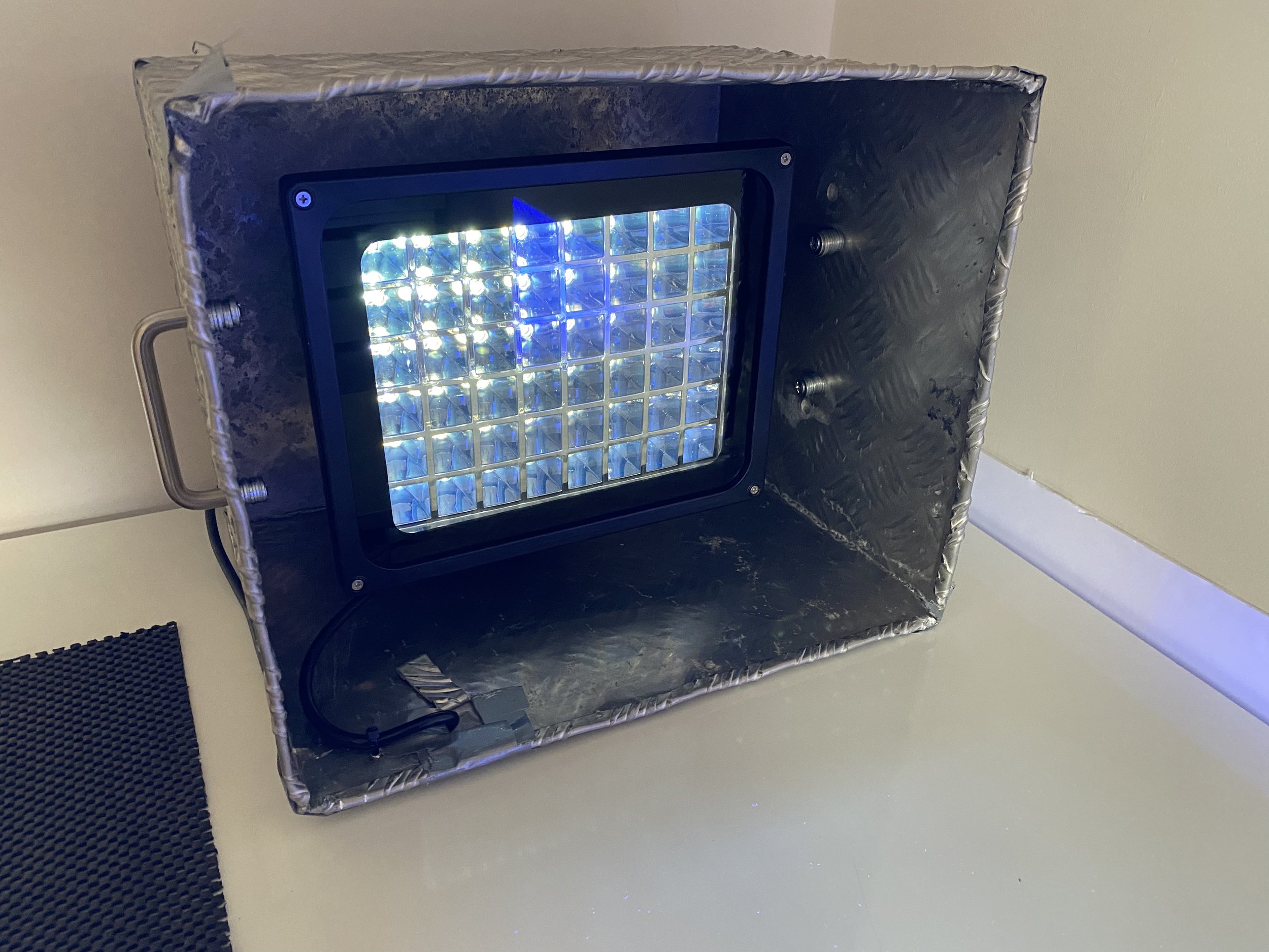
Most people I came across online built 365nm units using strips of LEDs (typically bought on 5m rolls) that can be cut to fit any size of box/enclosure. There were no suppliers in the UK that I could find though so I settled on a 365nm UV flood light that contained 18 LEDs giving a total power output of 50W. I had no idea if this was going to be enough to deliver reasonable exposure times or what those times might be. It was going to be a £200 ($260] leap of faith.
[EDIT: 50W is quite a powerful light source and is reflected in my low exposure times]
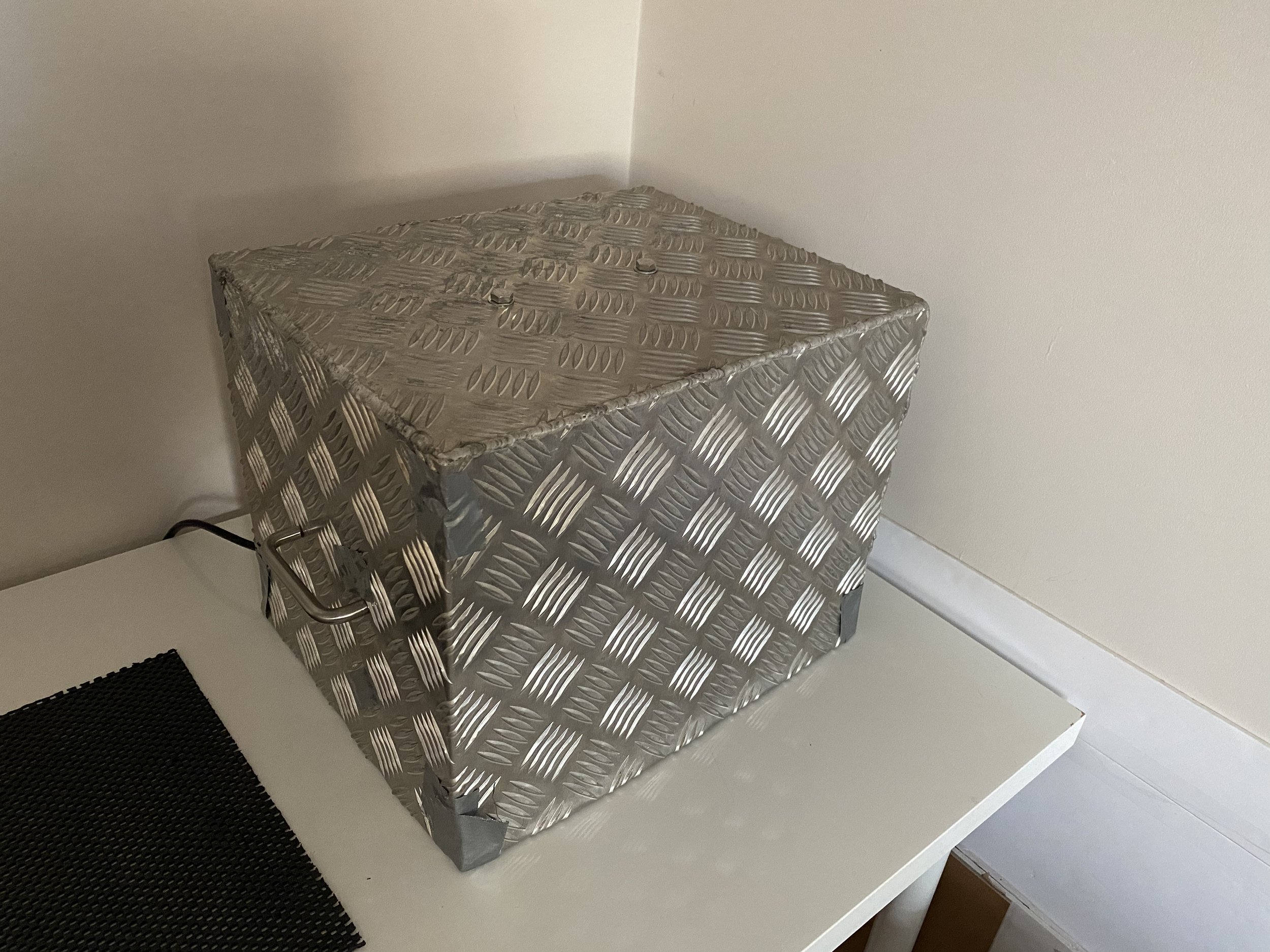
The light arrived and I bolted it into an aluminium box that had been sitting in the garden for a few years. I added some handles and I was ready to go. What I couldn’t find though was any sort of minute/seconds countdown timer that I could control it from – as in, press a button and have it countdown a chosen ‘on’ time. I still haven’t found such a thing so I have to use the switch on the extension cable I run it from, using my phone as a timer. I’m either Googling the wrong search term or such a thing really doesn’t exist. Either way, using a handheld timer is a pain and with my short exposure times (see below), is worryingly inaccurate.
[EDIT: How dumb I was… darkroom timers are ideal albeit quite expensive. I now have one from ebay.]
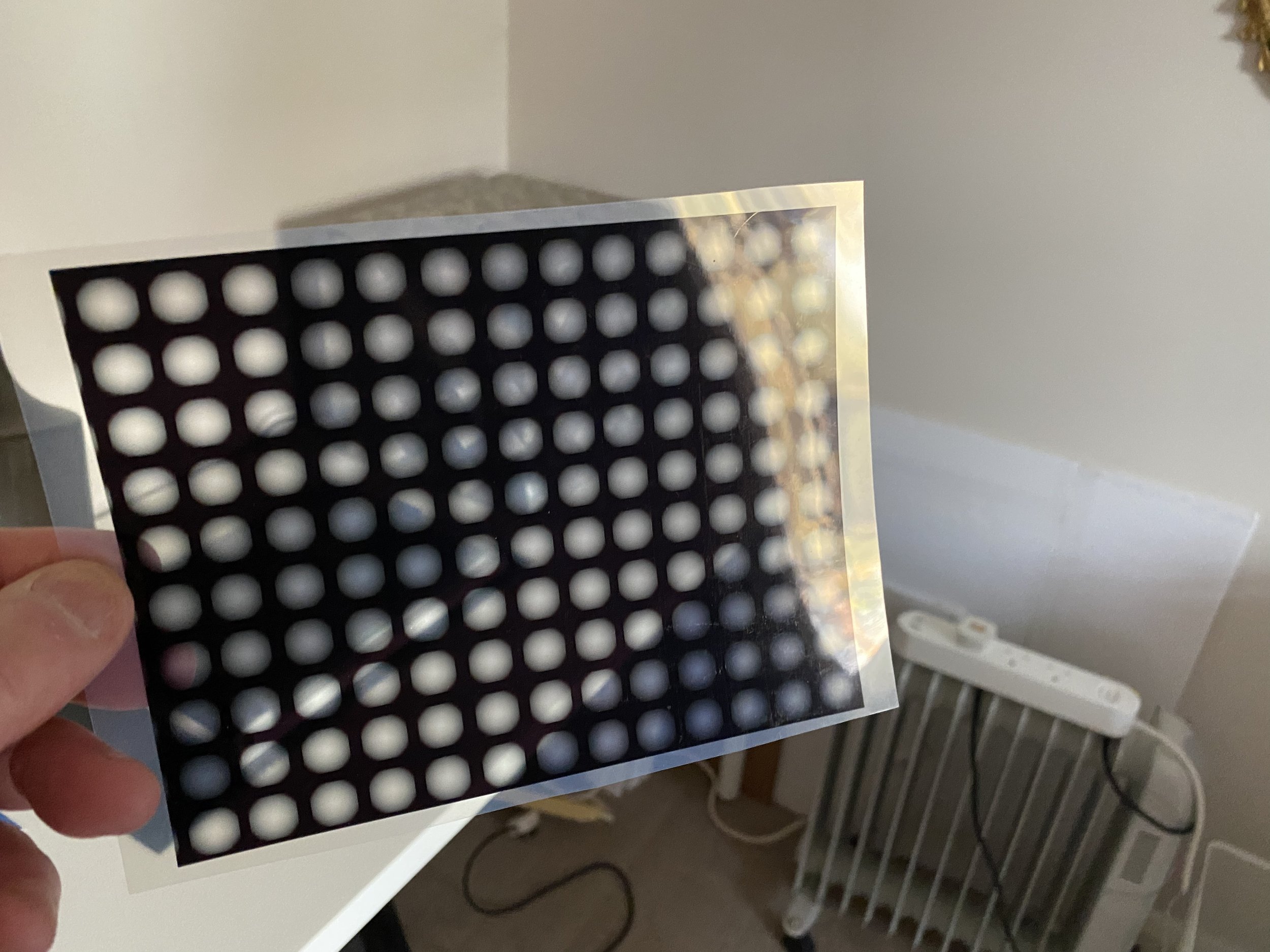
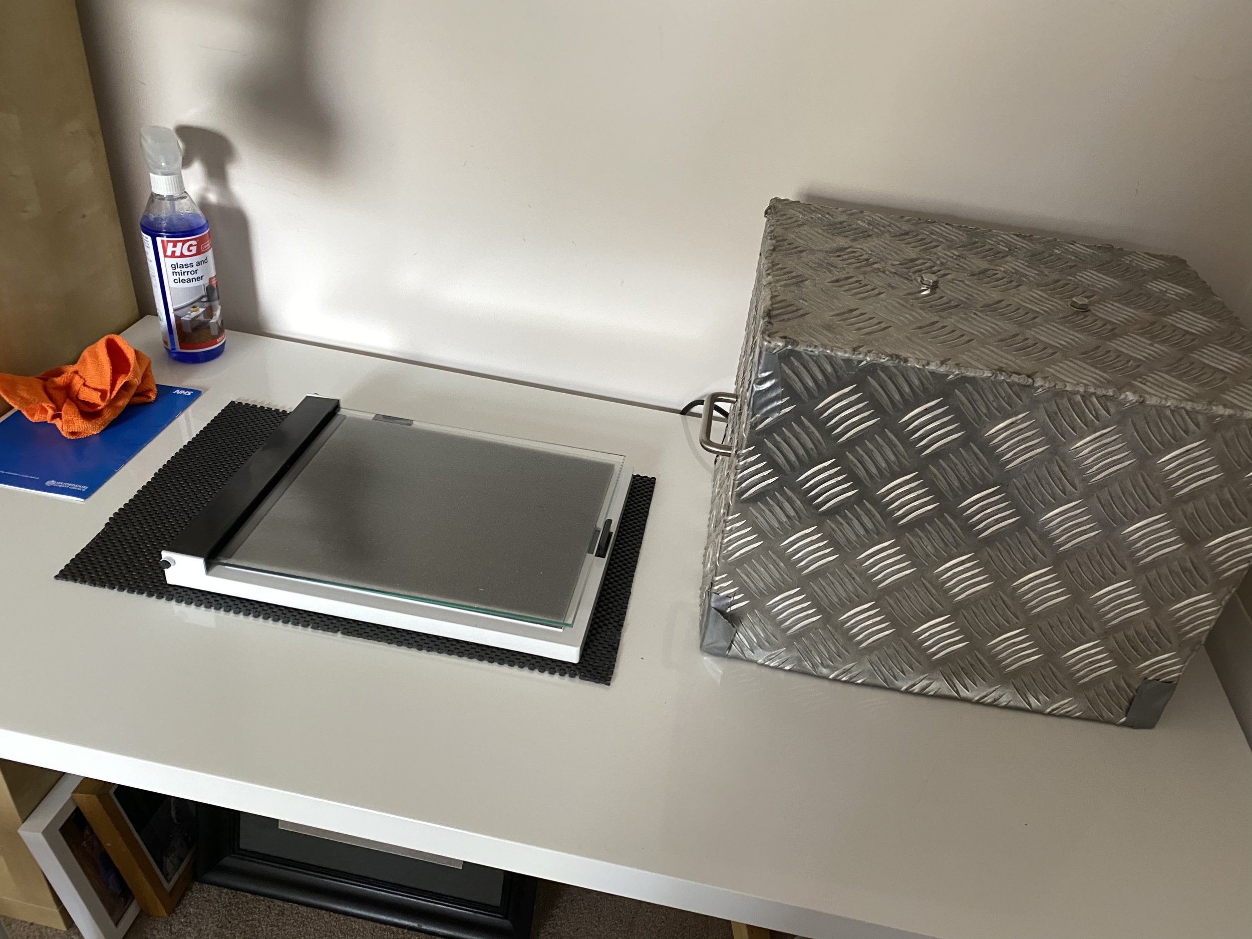
Using a 10×12” Paterson darkroom contact frame, I started making experimental Stouffer step tablet exposures on 1” strips of Toyobo KM73 plates. In essence and in practice, I was reproducing what had been doing at OPC. Expecting my exposure times to be long (for some reason I decided that my 50W LED unit was relatively low power) I started at 10 minutes as a base exposure time. I decided 50W was low power probably because I’d read about specialist 365nm LED strip-based units having seemingly ridiculously high wattage per square metre of power. I was to be proved very wrong on this. And If I’d thought about it and reflected on the fact that the specialist UV unit I’d used at the workshop required exposure times of 7 minutes or so, I might have believed that my unit was in fact HIGH POWER and therefore needed SHORT exposure times!
With results no better than with the metal halide UV unit at OPC with a 10 minute exposure time (why oh why did I decide to start with 10 minutes?), I increased my times to 30 mins, then 45… all the way up to several hours. All the while my test plates getting fainter and fainter.
In retrospect, I realised that I didn’t actually know what I was looking for in these exposed plates in terms of what they were actually supposed to look like when developed. This was a serious blunder on my part and it wasted me a very great deal of time (and expensive plates). It also reflected the fact that I wasn’t following (any more) a documented methodology and was flying blind. And I wasn’t looking at my results and thinking about what I was doing wrong.
[EDIT: I met a printmaker, Roxy, at OPC the other day who was also struggling with photopolymer printmaking who showed me her test plates and I finally understood what I was looking for re. Clay Harman’s “first Stouffer step-edge strip washed out to the bare metal”. Roxy had a test plate that showed actual bare metal. Aha! When Clay wrote “bare metal” I thought he meant ‘invisible in the polymer layer/film’. What an idiot I was. That’s how I wasted/blew six weeks right there.]
Ultimately, I decided that my light source was just not powerful enough to expose my plates in a practical/reasonable amount of time. I therefore decided to take the plunge and build a new (second!) UV unit using strips of 365nm LEDs. I also decided to sleep on this decision. This turned out to be a smart decision.
I then decided, as a final validation of my hypothesis that my 50W unit was ‘low power’ that I needed to run tests with times lower than my baseline 10 minutes. I also decided to abandon the Stouffer step tablet-based methodology and adopt Jon Lybrook’s approach that uses a simgla eimage to determone aquatint/image exposure times. The former was vital for scientific rigor and the latter was because I didn’t actually know what I was looking for. I was nowhere and I was floundering in other words. But… I now had a (new) plan!
More about this in ther next post.